THE truck frame is one of the most important components on a vehicle, acting as the backbone that carries the truck load.
In his presentation, “Preventing Costly Truck Frame Modification Mistakes,” Eddy Tschirhart of the Canadian Transportation Equipment Association dissected the frame, common errors that are made, and strategies to avoid that in the future.
Tschirhart said that for the most part, truck chassis are built with “ladder type” frames, side rails, and crossmembers.
Frames, Tschirhart said, are subjected to three types of loads:
• Vertical. “These are loads to the chassis frame from engine, transmission, fuel tanks, battery boxes, suspensions, bodies, and work equipment, along with cargo.”
• Torsional. “Torsional rigidity is provided by crossmembers, which also assist by supporting components such as the engine, transmission, and radiator. In addition, the crossmembers prevent the side rails from twisting with side loads such as the fuel tanks and battery boxes.”
• Side. “Side loading comes from fuel tanks, battery boxes, auxiliary equipment, such as hydraulic oil tanks, wet-lines, and auxiliary axles that are mounted to the chassis frame. It is imperative to have crossmembers located strategically, a caution to cover with wheelbase modification.”
He said frame issues can result from fatigue, stress, and workmanship. Here are some common problems:
• Bending is when the frame permanently changes shape. Bends are caused by static overload from too much cargo or impact from dropping a load onto the cargo body.
• Cracking. Frame rails sometimes crack because of a combination of fatigue, a high stress level, and in many cases poor workmanship. When the crack is between the axles, it usually starts in the bottom flange and then upwards through the web.
Tschirhart showed a photo of a frame that was cracked on or near the neutral axis, and said the frame had been welded across on the top side of the lower flange.
Dump bodies can be a challenge for truck frames. This is especially true as the dump body first begins to rise, before the load starts to slide back in the unloading process.
“Is there enough frame resisting bending movement?” he asked. “It could be a problem—especially in cases where a highway tractor has been converted to a straight truck.
Wheelbase changes also affect truck frames.
“In terms of wheelbase modification, believe it or not, that truck will have 60-plus items, being dimensions and equipment, plus related issues affected with the wheelbase modification.”
Tschirhart said many frame modifications are for special requirements such as frame drops—side loaders used for street pickup of residential refuse.
He provided some cautions regarding wheelbase alterations:
• With driveline issues, be sure to get set up to proper working angles.
• In a lengthening process, be sure to stay to driveline lengths recommended by the OE and the driveline manufacturer.
Anatomy of a frame
Tschirhart gave frame component descriptions, saying the web is “the vertical section of a frame rail” and the flange is “the horizontal section of a frame rail, located at the top and/or bottom of the rail.” (Related gallery: Helpful Truck Frame Terminology)
His tips on frame strength:
• A frame section supported at each end loaded in the middle is in compression at the top and in tension at the bottom.
• When a load is placed anywhere between the axles, the frame rails do two things. The weight of the load puts the bottom portion of the frame into tension. Simultaneously, the top portion of the rails is compressed. But along the middle of the frame rail, there is no stress. If the frame must be drilled or welded, this is the best place. Holes and welding near the flanges can cause frame failure because they weaken the frame at exactly the place where the loads are greatest.
• Chassis manufacturers restrict the size and location of holes. Most OEMs also restrict welding on their frames.
Do you have a moment?
Tschirhart said moments are force, or weight, times distance. One pound times one foot is 1 ft-lb. One pound times twelve inches is 12 in-lbs. They are both the same moment. Moments on a truck frame can be measured from the front axle, the front of the frame, or any other point as long as all forces are included. Up forces are positive and down forces are negative.
With the same load, the maximum tractor moment can be as much as twice the straight truck.
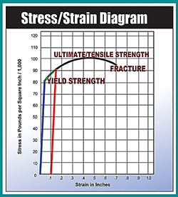
He said yield strength defines the material.
“It is the maximum stress that the material will sustain without permanent distortion,” he said. “It is related to ultimate strength. Typical values are: 31,000 to 35,000 psi for mild steel to 110,000 psi for alloy steel, and over 110,000 psi for heat-treated steel.
“When mixing materials of different yield strengths, the lowest value must be used for calculations.”
Section modulus defines the shape of the frame material in inches cubed. It is related to the moment of inertia and stiffness. Published literature can be as much as 30% too high.
Frame considerations
He said RBM is the resisting bending moment and is the product of the section modulus and yield strength in inch-pounds and is a measure of the capability of the frame rail.
“Some manufacturers of equipment such as cranes specify either a section modulus or RBM for the chassis frame,” he said. “Chassis manufacturers supply frame information with RBM, section modulus, and yield strength in truck data books and body builders books.”
RBM describes the ability of the frame to resist the moments from the load and truck components, section modulus describes the shape of the material, and yield strength describes the material strength. Moment equals SM times stress, and stress equals moment divided by SM.
“When frame length changes are within the chassis manufacturers’ wheelbase for that frame, maintain RBM,” he said. “Adjust the yield strength to allow for weld splice—example, 25%—and add RBM with reinforcements to maintain the original RBM. The resulting RBM should equal or exceed the original RBM.”
Example:
• Original RBM = 1,000,000 in-lb.
• Using 25% for the weld, strength at the splice reduces the RBM to 250,000 in-lb.
• Add a reinforcement of 750,000 in-lb to attain the original RBM of 1,000,000 in-lb.
He said the ultimate/tensile strength is the maximum stress before failure by separating. Typical values are: 36,000 YS, 110,000 YS, 50,000 US and 135,000 US.
The design factor is multiplied by the maximum load to determine the needed RBM; 2.5 to 3 are typical.
Dynamic loading are loads put into a frame from acceleration, braking, road irregularities, etcetera.
Fatigue is the behavior of a material which when subjected to cyclically applied stress can result in a crack and failure.
Stress concentration is a sixth-power effect when the stress level is above the endurance limit. Doubling the stress decreases the life by a factor of: 2x2x2x2x2x2 = 64. A 300,000-mile truck becomes a 5,000-mile truck. Increasing the stress by 12% decreases the life by one half. Decreasing the stress by 12% doubles the life.
Terms to remember
Tschirhart listed several terms commonly associated with fatigue of the frame:
• Endurance limit is the maximum stress that a material can tolerate indefinitely without failure.
• Fatigue strength is the stress level corresponding to a definite life.
• Stress concentration is a hole, weld, crack, notch, or other discontinuity that concentrates stress. An open hole concentrates stress from 2.5 to 3 times. A grade 8 bolt reduces the concentration to 1.5 to 1.9.
“Stress concentrations cause problems,” he said. “At 40,000 psi, the material has an infinite fatigue life––it will not fail because the level of stress is below the endurance limit.
“If a weld or a hole concentrates stress by doubling it, the level raises to 80,000 psi. The part now has a life of 100,000 cycles. The 100,000 cycles is well within the normal life of a truck chassis.”
He said moment of inertia is a mathematical representation of the shape of a frame rail. As wheelbases get longer, deflection becomes more important. The rule of thumb is that with WB under 160”, design for strength. With WB over 160”, design for deflection.
For the same load, a 10% increase in wheelbase requires a 10% increase in RBM for strength and a 33% increase in moment of inertia for the same deflection.
Watch what you weld
Welding on frames presents problems. Here are some things to remember:
• Lack of penetration on one or both pieces is the major problem at all levels—manufacturers, distributors, and repair.
• Weld quality is improved with better control. Manufacturers do the best job, followed by distributors and, lastly, repair shops.
• Poor welding can lead to failure in the field.
How to splice frames:
Tschirhart provided these tips for those who must splice (and weld) truck frames:
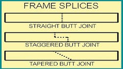
• Don’t go from stiff to flexible; taper and stagger reinforcements.
• Stay out of high-moment areas or extend reinforcing to a lower moment area.
• Match steels for yield strength as closely as possible and use the lower yield strength for calculations.
• Extend reinforcements a minimum of twice the frame height past the splice before beginning the taper.
• The strength of a frame rail is in the flanges.
• More steel is stronger than less steel.
• Use a straight cut at the splice.
• Be thorough with the weld prep.
With frame welding, use heat sinks. Copper is preferable, and aluminum has been used in some cases. They dissipate/shorten up the heat-affected zone in the frame caused by the welding process. If you are interested in using them, be sure to try the process and perfect before working on a customer’s truck frame. ♦
About the Author
Rick Weber
Associate Editor
Rick Weber has been an associate editor for Trailer/Body Builders since February 2000. A national award-winning sportswriter, he covered the Miami Dolphins for the Fort Myers News-Press following service with publications in California and Australia. He is a graduate of Penn State University.


