It’s not just the weight of the truck—it’s how that weight is spread around. The commercial truck upfitter should be able to help.
WHEN you’re in the process of designing a new truck, it’s important to ensure that equipment and payloads can be safely and legally positioned while meeting the vehicle’s Federal Motor Vehicle Safety Standard (FMVSS) and weight law requirements.
Weight distribution and payload calculations are key factors in preventing overloading, which can cause problems for end users and equipment installers.
In “Work Truck Weight Distribution and Payload Calculations Made Simple,” Steve Spata of the NTEA’s Technical Services division went through sample weight distribution calculations and provided software tools designed to help perform complex vehicle calculations relating to FMVSS compliance calculations.
The W’s of Weight Distribution, in actuals versus limits:
• Total loaded weight of vehicle versus Gross Vehicle Weight Rating (GVWR).
• Actual weight on front and rear axles at the tires versus Front and Rear Gross Axle Weight Rating (FGAWR & RGAWR).
• Location of center of gravity versus OEM limitations for CG dimensional position (horizontal, vertical or lateral)
“We need to do weight distribution calculations to meet customer application requirements, to comply with Federal Motor Vehicle Safety Standards, and to comply with federal/state/municipal weight limits,” Spata said.
“Weight distribution calculations should be done as early as possible, and ideally before a chassis is selected for the work truck application.”
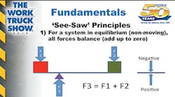
He said the “See-Saw” Principle is one of the fundamentals: For a system in equilibrium (non-moving), all forces balance (add up to zero), and all moments balance (add up to zero). Moments are a force or weight times a distance. Counter-clockwise is a negative moment and clockwise is a positive moment.
“Moments, like forces, have a direction,” he said. “Think moments, clocks.”
Center of gravity is the “point at which the entire weight of a body may be considered as concentrated so that if supported at this point the body would remain in equilibrium in any position.”
“The center of gravity of a collection of masses is the point where all the weight of the object can be considered to be concentrated,” he said. “Being a ‘point’ means a three-dimensional position, but not necessarily part of the physical object—like a hollow ball has the same center-of-gravity location at the center just as a solid one.”
The center-of-gravity position in each dimension is calculated by averaging moments from all the “chunks”—weight times location (relative to the same plane) divided by total weight. To get center-of-gravity locations for ‘chunks’, use info from manufacturers, body builder information, or the best estimates.
Where should the CG be on a work truck?
“Horizontally, we want it between the front and rear axles,” Spata said. “The closer the CG gets to a specific axle distributes more weight to that axle. We need to stay within all axle ratings when the truck is loaded.
Important notes
Something important to note about typical GVWR specs between light and heavy chassis:
• Light chassis GAWRs add up to a value higher than the GVWR assigned. This gives freedom for where the overall center of gravity can be located when the vehicle is loaded to full without exceeding axle ratings.
• Heavy chassis GVWR spec’d at the sum of axle ratings—this dictates where the overall center of gravity has to be when loaded.
• Vertically, we want it as low as possible, and within limits set by the chassis OEM. However, longer wheelbase vehicles can have a higher limit set by the OEM to aid in dynamic weight transfer to the front axle during braking.
• Laterally, we want it as close to the centerline of the vehicle as possible. Too far one side or the other can exceed corner weight limits.
FMVSS considerations:
• Brakes, tires, and rims are regulated by FMVSS 105, 109, 110, 119, 120, 121, 135, 139. The completed truck must comply with each of these.
• Horizontally, axle loads need to be within front/rear GAWR.
• Laterally, corner weights should be within one-half of the GAWR for that axle.
• Vertically, the CG must be within limits set by the chassis OEM.
For light trucks with a GVWR of 10,000 pounds or less:
• The Maximum Unloaded Vehicle Weight (MaxUVW) is a key weight characteristic used for FMVSS compliance. MaxUVW is the heaviest curb weight you can have for the completed vehicle (no people, no cargo) with traceability back to successful OEM testing.
• From NHTSA CFR 49 Part 571.3: Unloaded vehicle weight means the weight of a vehicle with maximum capacity of all fluids necessary for operation of the vehicle, but without cargo, occupants, or accessories that are ordinarily removed from the vehicle when they are not in use.
• Crash and related safety standards that the truck must meet include FMVSS: 126, 208, 212, 214, 216, 219, 226, 301.
• From a safety standpoint more weight equals more kinetic energy to manage away from occupants.
• 3D center-of-gravity position affects crash performance and roll stability functionality.
• Multiple center-of-gravity caution: FMVSS 126 Electronic Roll Stability has led to more restrictive center-of-gravity positional limits than for FMVSS 105 Hydraulic Brake Systems.
• Multiple MaxUVW caution: Newer EPA emission regulations leading to lower MaxUVW than for crash and dynamic safety standards testing.
• Consult chassis OEM incomplete vehicle documents and body builder information. When a range is given, use the lower of applicable limits.
For light vehicles, compare curb weight to MaxUVW. The curb weight is the upfit weight (body and/or equipment) plus the base chassis or original vehicle weight.
Heavy-vehicle considerations:
• Bridge Law: After designing a vehicle to respect chassis limits, the Bridge Law is for respecting pavement/infrastructure limits. “More weight on fewer axles, and closer together, is bad.”
Spata said there is a free calculator available on the Federal Highway Administration (FHWA) website: http://www.ops.fhwa.dot.gov/freight/sw/brdgcalc/calc_page.htm.
For a GVWR of 8800 pounds with a base vehicle weight of 5000 pounds, an upfit weight of 1500 pounds and occupant weight of 300 pounds (two seats at 150 pounds each), the cargo capacity would be 2000 pounds (which is 8800 minus 6800).
“Compare cargo capacity to customer requirements and include in the vehicle placard with the occupant weight,” he said.
He said the federal bridge limits are: 20,000 pounds for single axle; 34,000 pounds for tandems; and 80,000 pounds total. The allowed weight across consecutive axles increases with the number of axles and spacing between them.
“After performing a weight analysis to determine axle loading, compare results to the bridge chart column for each grouping of axles,” he said. “The ‘outer bridge’ refers to distance in feet from the foremost to rearmost axle centers.
“Where axle weights would exceed federal, state and/or local weight limits, what are some options to consider? Potential solutions: lengthen the wheelbase to increase outer bridge and/or inner bridge spans between consecutive axles; reduce and/or redistribute cargo; add additional axles. Note that this assumes no increase in GVWR.” ♦


