WHY is it important to know about chassis changes?
Because knowing what is required for a specific installation or upfit can help you profitably quote the job. In addition, unexpected issues in the shop cause delays and add cost to the job, and can delay the customer’s vehicle.
And then there’s the most important reason: Each new model year, there are improvements and changes to chassis that affect the installation of common bodies and equipment. Knowing these issues in advance can help you properly quote the job and be prepared for efficient installation to save your bottom line.
In a National Truck Equipment Association webinar, “Chassis Changes and Your Bottom Line,” NTEA director of technical services Bob Raybuck, went through changes for the 2014 model year for GM and Ram.
He said GM is using a new method for aftermarket trailer brake controller wiring on the C/K 1500.
“In the past, aftermarket trailer brake wiring was standard on all pickups,” Raybuck said. “Today, the chassis manufacturers have been offering integrated trailer brake controller systems, and these systems tie into the anti-lock brake system to help control potential trailer slide. Because of this integration, OEMs need to have a different path for aftermarket trailer brake controls in order to separate them from the actual trailer brake system. We’re seeing different formats to take care of this. So an upfitter has to add the provisions. The GM C/K 1500 is the only half-ton pickup available for box removal.
“It’s also important, when quoting your upfit, to ask if the pickup has an integrated brake controller or you have to be prepared for the extra time to wire in the controller. It’s important to know what extra time you need for wiring and what extra parts you need for this wiring system.”
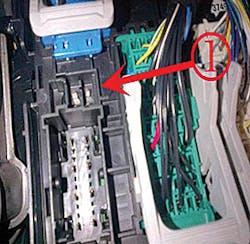
Raybuck said that right behind the parking brake pedal is a small junction box, and underneath that is a spot to plug in the trailer brake controller piece itself.
To connect a trailer brake controller, a harness is needed that will plug into the X6 position of the Left I/P Junction Block (X61A), located under the driver’s side dash near the parking brake pedal assembly.
He said GM recently introduced an aftermarket trailer brake controller jumper harness for the new 2014 1500 series pickup trucks, and it’s now available. This ready-to-use harness (P/N 23184088) can be obtained at area GM parts departments.
“Any dealer-purchased parts add expense to your bottom line,” Raybuck said. “If you know you need to add an aftermarket brake controller as part of the upfit or body installation, make sure you account for the additional parts and labor necessary starting with the 2014 model year. Or, as an upfitter, talk to your trailer brake controller supplier. They probably will be prepared for this and probably will start having these harnesses as part of the system as well.”
He said LED lighting has always been “a unique and interesting issue.”
“We get a lot of phone calls about LED lighting because in the lighting standard for vehicles, FMVSS 108, there is a requirement that there is a bolt connection system for any vehicle over 10,000 pounds,” Raybuck said. “The standard itself allows vehicles that are equipped with trailer towing systems to actually have the bolt detection turned off. As the pickup comes from Ford, GM, or Ram, it requires the detection system as a standard item on each vehicle. Because of LED lamps, you will have to add additional resistors or request the dealer to reprogram the system in order to change the function for LED lamps.
“GM is unique. The stop and turn lamps can come in two configurations: one lamp per side or two lamps per side. This is important because if you’re doing a resistor system, you need to know how many lamps per side.
“Chassis cabs and factory pickup box delete can be ordered with LED lighting provisions. But’s it’s only available for 2500 and 3500 vehicles at GM. The GM C/K 1500 cannot be reprogrammed for LED lighting. Additional resistors are required. You have to be aware of that in advance.
“As an upfitter, you want the dealer service bulletin. If you need to have it reprogrammed and you send a customer to a local dealer and it’s not the dealer you’re used to dealing with, they may not be aware of how to reprogram it. You go to the service department and the service manager says, ‘Here’s the high cost of doing it because we have to look up the calibration.’ If you take this bulletin with you, it gives them the actual service bulletin information and from that they can automatically draw the calibration easily. That helps lower your costs because you’ve made it easier for the dealer to help you.”
Raybuck said that for 2014, GM has added configurable upfitter switches to the C/K 1500 work truck that can be configured in either “ignition hot” or “battery hot.” The new 2015 C/K 2500HD and 3500HD will be available in early 2014 with this same upfitter switch system.
To configure these systems, go to the Underhood Electrical Center.
“Two little prong fuses are already configured to be ‘battery hot,’ ” he said. “As ‘battery hot,’ any time you turn on the switch, anything connected to it will work completely. If you move either one of the fuses, you switch from ‘battery hot’ to ‘ignition hot.’ You can do in any combination.
“In the vehicle itself, behind the parking brake pedal, you physically connect to the upfitter switches. In the system itself, they use pins 1, 4, 14, and 20 to designate 1, 2, 3, and 4 on the upfitter switches.
“Behind the brake pedal on the inside of the vehicle, there is a rubber connection. This is where you have your pass-through availability. With GM, they set it up so you can pass through any wire you want.”
He said GM has released bulletin No. 108, which deals with connecting aftermarket items to the datalink connector.
“It’s not uncommon for your suppliers to say, ‘Oh, here connect this,’ whether it’s an aftermarket cruise control or the datalink connector itself,” he said. “It’s important to understand that GM is saying in this bulletin that they don’t authorize this. And they may not cover the warranty related to any issue that can deal in electronics through the datalink connector.”
Raybuck said Ram lights are controlled by a computerized module called the Central Body Controller (CBC). The module controls the left front, right front, left rear, and right rear lighting independently.
The CBC utilizes “smart” technology that has the ability to monitor the current (amperage). The monitored outputs include the headlamps, turn lamps, stop lamps and reverse lamps
“Headlamps are important for those dealing with snowplow installation,” he said. “A customer may say, ‘Hey, I want to transfer this plow from 2009 Ram to this vehicle.’ Well, the wiring is probably going to have to be changed completely.”
The module has a preset allowable current (amperage) operating range for each of these outputs.
If while in normal operation the current detected falls outside this preset range, then a fault is set in the module. In the case of too high of current, the circuit will be shut off. You can also get into these fault conditions by adding additional lamps to the circuits or by changing the lamp specifications (ie, changing the type of lamp used). In the case of the turn lamp circuits, if the module detects too low of current then the module will assume an open circuit condition (burned out bulb), and the blinker will flash at a double flash rate.
Customers sometimes desire to add additional lamps to the exterior lighting circuits. This is possible but requires adding a relay to control the additional lamps. By correctly wiring the relay into the lighting circuit, you only add the additional coil resistance of the relay. This will maintain the correct operating current (amp) range of the circuits and no faults will be set. A relay will need to be added to each side of the vehicle (left and right).
For 2014, there are three methods to eliminate fast flash and error codes when replacing rear stop/turn incandescent bulbs with LEDs:
• If the vehicle is equipped with the VSIM (Vehicle System Interface Module), then ground circuit W509.
• Ground circuit L950 LG/WT located in the driver side fender inner. The circuit is accessed by removing the PDC in front of the battery and reaching into the fender inner.
• Add power resistors to the rear light circuits.
If you are keeping the original incandescent lamps (or the aftermarket equivalent) and you want to add additional LED lamps for use as stop, turn, reverse or park lamp function, you can do so with no additional changes to the vehicle or its electrical system.
Five switches are located in the lower switch bank of the I/P—all are auxiliary (AUX). Switches AUX 3, 4, 5 are set to ignition; AUX 1 and 2 can be either battery or ignition (customer choice via 5A fuse). Fuse sizes (rating) for the switches are customer choice via fuse relocations. Connections to the switches are found under hood in the gray connectors attached to the auxiliary PDC. AUX 3, 4, 5 switches will maintain “last known state” functionality; AUX 1 and 2 will not.
The AUX Switch PDC contains eight fuses: five for the auxiliary switches; one for the 20-amp upfitter battery feed; one for the 20-amp upfitter ignition/run feed; and one for the 5-amp mini fuse that can be customer-located in its holder to allow changing switches 1 and 2 from ignition feed to battery feed. The PDC houses six relays: five relays are for the auxiliary switches and one provides the 20-amp upfitter ignition feed.
The 40A, 25A, and 20A fuses can be moved as desired to any of the switches 1, 2, 3, 4, or 5. These fuse “sizes” are for identification purposes only. Refer to the Chassis Cab Upfitter Schematic in the Upfitter Wiring Interface.
Raybuck said the AM Optional VSIM provides a multitude of useful I/Os to increase upfitter friendliness and upfit simplification. Vehicles not ordered with this option from the factory cannot be retrofitted. Its sales code is “XXS.”
“Over 55 electrical upfitter interfaces are available,” he said. “You can physically attach and work with and it improves your bottom line because it’s faster and simpler to wire into this system.” ♦
